

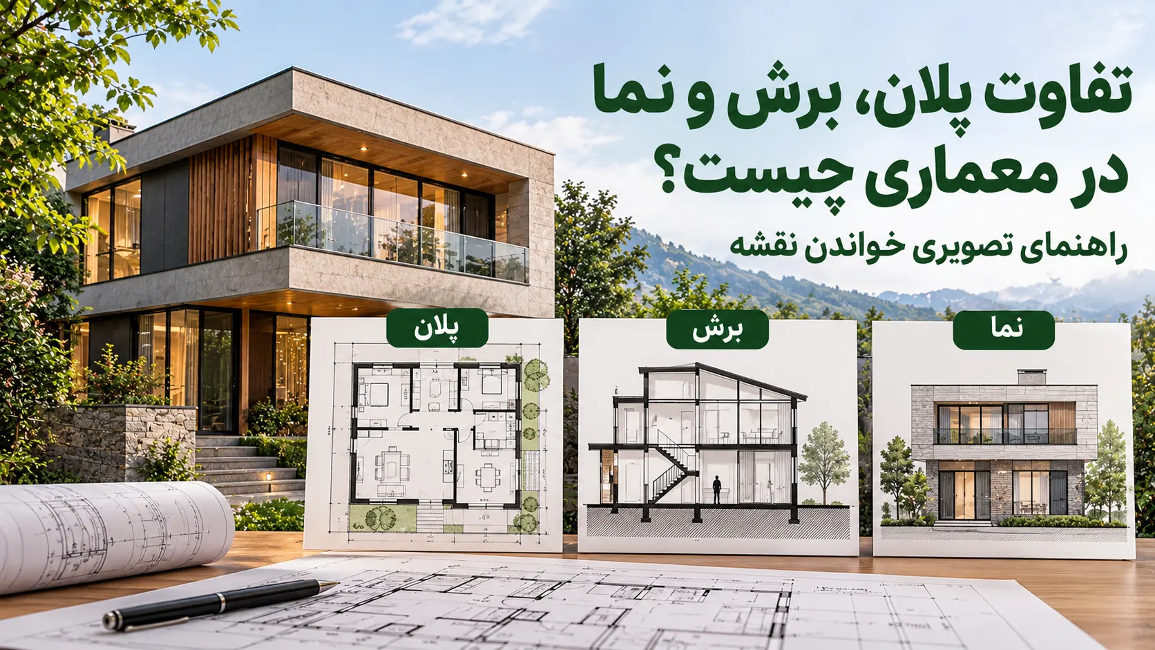
A plan, section and elevation can describe the same building in different ways. A plan usually shows a horizontal cut viewed downwards; a section shows a selected cut, commonly vertical; an elevation shows a face without cutting through it. The examples below are from different buildings, not one coordinated set.
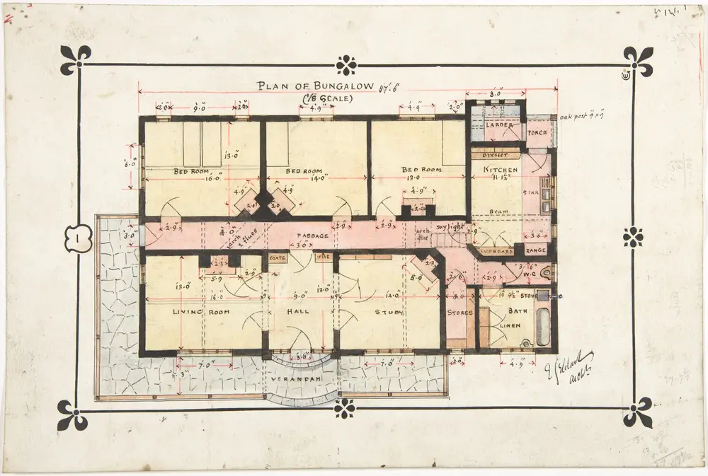
Plan: relationships at one level
A floor plan shows spatial arrangement and circulation at a chosen level. Walls, openings, stairs, furniture and annotations can all appear, so read the drawing title and legend. The cut height and conventions depend on the drawing’s purpose and standards.
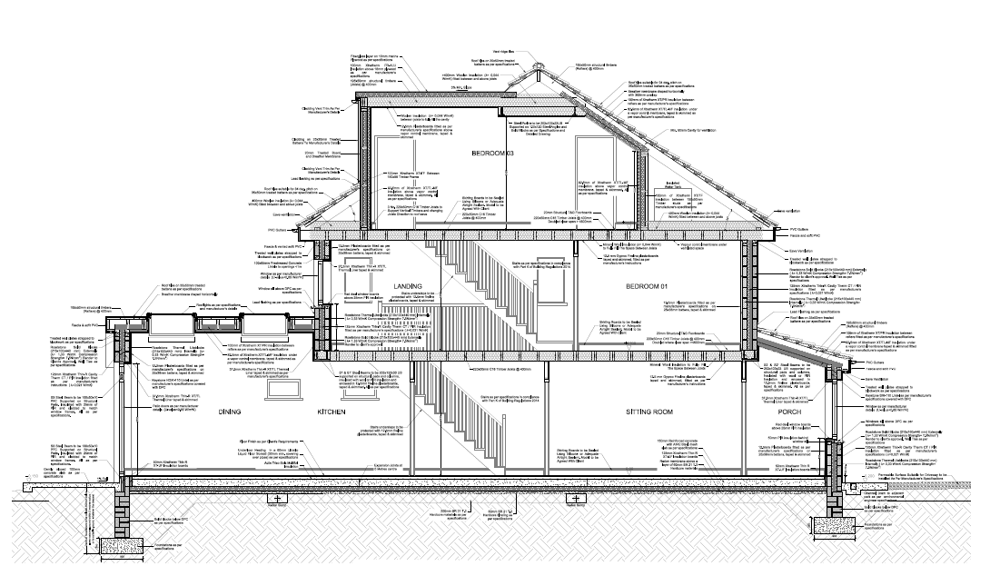
Section: relationships in height
A section cuts through a chosen plane, usually vertically, revealing relationships between levels, stairs, roofs and other elements. Find the section marker and viewing direction on the plan, then match its identifier to the section drawing. Elements cut by the plane are usually differentiated from those beyond it; consult the set’s legend.
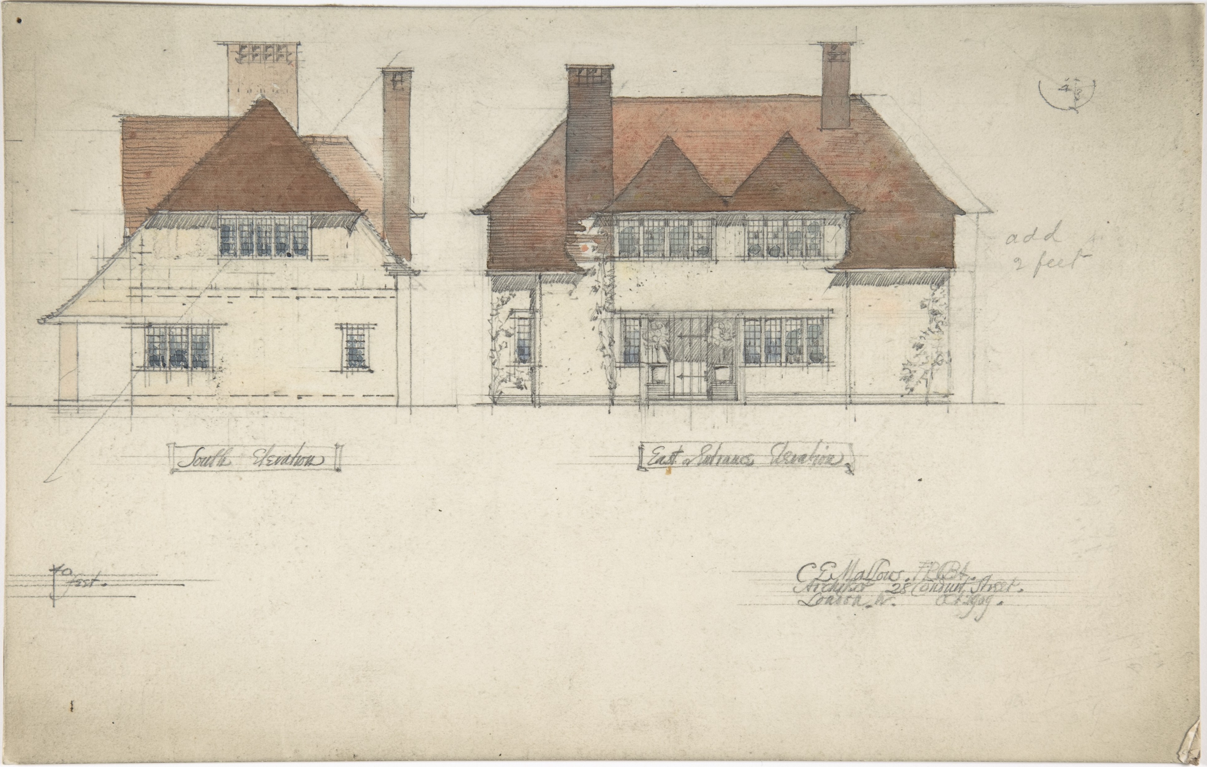
Elevation: a face without a cut
An elevation is a direct representation of an exterior or interior face. It shows the arrangement of openings and surfaces, but use plans and sections to understand depth and what lies behind it. The direction in its title identifies the face, not necessarily the building entrance.
Read the drawings together
Check project, date, drawing revision and level. Find a window or stair in the plan and identify the corresponding elevation or section. A section only depicts the selected cut and what is visible beyond it. At 1:100, one centimetre on a correctly scaled print represents one metre; a resized PDF or print can invalidate ruler measurements. Check written dimensions and resolve discrepancies with the responsible designer.





No comments yet. Be the first.